As engineers, we’re constantly tasked with making the impossible not just possible, but reliable and repeatable, especially when it comes to building bridges over deep water. These projects push us to solve problems where there’s no solid ground to start from, where every decision must factor in extreme depths, unpredictable weather, shifting sea-beds, and the relentless force of water. But that’s exactly why this kind of work matters. It forces us to rethink stability, safety, and precision in entirely new ways. What we build isn’t just concrete and steel, it’s trust, resilience, and connection. And for any engineer navigating this terrain, the real challenge is staying grounded in the fundamentals while also embracing the evolving methods that make this kind of work not only achievable but sustainable in the long run.
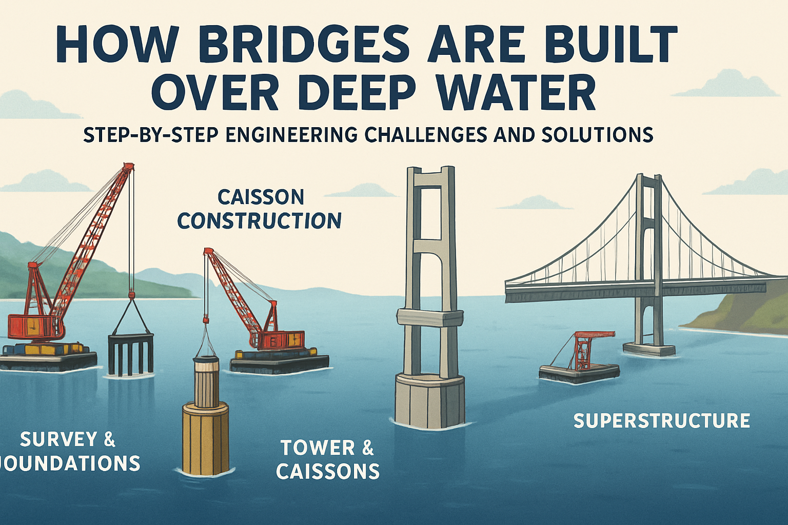
Please take a look at the foundations of a modern bridge. How are such gigantic foundations built, especially when they stand on long concrete piles? Remember, the foundation is half submerged. To construct the foundation, engineers first need to install a watertight chamber, a caisson.
Let’s observe the installation of this massive structure. Can you spot a major issue in this installation? Water enters through the pile caisson joints, and the entire caisson is flooded. Think of a solution here. The engineer simply extended a few pipes outside the caisson. Now when they’re inside the caisson, the leaked water will stay inside these pipes, and the workers can easily do the foundation work in the dry area of the caisson. The long concrete piles we saw at the beginning do not stop at the ocean bed. These long concrete piles travel through the ocean bed and extend even past the hard stratum.
They were constructed by pouring concrete into these steel casings. The big question is how do you erect such a lengthy casing? No crane in the world can accomplish this task alone. Engineers used a crane and vibro hammer together to accomplish this almost impossible-looking task. The crane first carefully positions a steel casing as shown. Here comes the vibro hammer. If you look closely, you can see this machine is vibrating intensely but with low amplitude. The vibro hammer pushes the hollow casing into the ocean bed. The vibrations of the casing make the piling process much easier.
Installing Steel Casings and Drilling Through Hard Strata
Now the crane carefully places the next casing above the previous one. They get locked together. The vibro hammer, holding onto the second casing, starts driving. Once the second steel casing is also fully inserted, a third casing is connected to it. This time the casing cannot go much farther down. It has hit the hard strata. However, the engineers want the concrete pile to extend below the hard strata as well. How do they do it? They first remove the soil inside the casing using an auger. Now a powerful machine called a cluster hammer begins its operation. Look at this drill bit with powerful teeth. The interesting thing about this machine is that the drill bit rotates and simultaneously performs a hammering action. This helps the drill bit break and pulverize the rock below.
Here’s the challenge. How do you remove the resulting debris? This is why compressed air is used. The compressed air passes through this narrow tube and finally reaches the teeth of the drill bit. The rock particles formed after hammering move along with the compressed air and reach this hollow central shaft. Finally, all the debris is safely collected in this box.
Now everything is clear for concreting. This long cavity, which starts from the hard strata and extends even above the ocean surface, is filled with rebar. Such long pile holes are generally concreted using the tremie method. This way, air gaps in the concrete mixture can be avoided.
How Modern Bridges Are Built Over Water: Foundation, Piling, and Girder Installation
Did you notice something strange in the concreting? They never fill the concrete into the last steel casing section. We’ll learn the reason for this later. Many such piles are erected on the ocean bed. Now it’s time to introduce the biggest steel structure of this project, the caisson. We’ve already seen the details of caisson erection and the importance of these protruding casings.
The first step before caisson insertion is to remove the last sections of steel casing we erected. This is why we didn’t pour concrete inside them, for their easy removal. Now the caisson is slowly inserted onto the piles we’ve already erected. The watertight joints of the caisson will ensure that a sturdy platform is ready for the workers so they can start the main construction. The details of the rebar arrangement for the foundation concreting are shown here.
Jump Form Technology and Pier Construction
Once the foundation is ready, the workers remove the caisson. For the concreting of such a long pier, engineers use an interesting technology called jump form. Here, the first concrete pour is done in a normal way. The forms that are attached now are mechanized. There are forms on all four sides. For simplicity, we’re only showing one. Once the concrete has hardened, this interesting technology comes into action. With the help of this lever, workers first separate the form from the concrete. Look at this attachment below the forms. This is hydraulically powered. When the engineers activate it, the form starts its climb. In a few strokes, the form will cover the entire height of the hardened concrete.
Now the workers can close the forms onto the pier and start the next stage of concreting, and this cycle repeats. The pier is growing slowly and steadily. Why did the workers suddenly stop the concreting here? They’re reducing the size of the pier. After the size reduction, the jump form concreting resumes. We’ll find out the reason why they reduce the pylon size very soon. When the pylon is nearing its full height, the workers insert saddles. This is a crucial component for future cable installation.
Now we’ve constructed one tower for this bridge. The workers have to construct three more such towers. It’s a magnificent sight to see all the towers standing strong in the water. They are waiting for the road deck to be installed.
The tendons reach the other end of the HDP pipe. After that they pass through the holes of the saddle. The tendon cables reach the other end of the saddle and travel through the HDP pipe again. After a long journey they eventually reach the other steel anchor. Here the tendons are tightened with the help of a stressing jack. Now the road deck is properly supported. The post-tension tendons are compressing them and bonding them together and the cable support from the top gives them much needed stability. Cable support is needed after every other girder.
The way the road deck progresses looks beautiful. Even the other tower girder assembly progresses using the balanced cantilever construction method. Eventually both the cantilevers meet in the middle. The last segment of the road deck is again fabricated using cast and C2 techniques.
This bridge which is located in Goa, India has a very gradual connection with the land. What we have just constructed is called a cable bridge. Driving across this bridge offers a blend of modern engineering and scenic beauty. Cable-stayed bridges have taken the civil engineering world by storm. Their popularity increased drastically after the 1950s.
Types of Cable-Stayed Bridge Designs
However, you may have seen a totally different type of cable-stayed bridge in your city. Here is one such bridge completed in 2009 with a total length of 5.6 km. Look at the tower or pylon of this bridge. This kind of design is called a diamond pylon. Moreover, this bridge is not purely a cable-stayed bridge. It’s a hybrid bridge. One portion of this bridge is cable-stayed and the other portion is a normal beam bridge.
Diamond pylon bridges have high geometrical stiffness. They’re also aesthetically striking. In fact, cable-stayed bridges can have five major types of pylon designs based on the situation. The third pylon design is called the H-frame design. The H frame consists of two vertical columns connected by a horizontal cross beam near the top or middle. They offer good lateral stability and are ideal for bridges with balanced spans on either side.
The Zensa bridge in Germany is quite unique. This type of cable-stay design is the A-frame design. This design transfers the load more efficiently to the base. Horizontal cross beams are generally not needed for this design. This design may look similar to the A-frame design but here the legs diverge downward from a single shaft, creating an inverted Y. The Guadana International Bridge in Portugal follows this design. We’ve already seen the I-shaped cable-stayed design. Here a single narrow vertical tower rises from the foundation. The I-shaped design is obviously the most minimalist one. This kind of cable arrangement is called a modified fan arrangement.
How Modern Cable-Stayed Bridges Are Designed, Built, and Evolved
There are two more ways to arrange the cables for a cable-stayed bridge. The other two designs are fan and harp arrangements. With all this knowledge we’ve accumulated, now let’s understand the engineering behind the longest sea bridge in the world, the Hong Kong Zhuhai Macau bridge. The length of this sea crossing is a whopping 55 km. This marvel of civil engineering features four artificial islands, one underwater tunnel and three cable-stayed bridges.
The longest section of the crossing is this roadway with a length of 29.6 km. The three cable-stayed bridges are part of this long section. Then starts the underwater tunnel, 6.4 km long. You can see two artificial islands at both ends of this tunnel. Now the journey continues on a 12 km elevated roadway and eventually we reach Hong Kong.
Cable-stayed bridges are exploding in popularity. Even though cable-stayed bridges are typically meant for a span range of approximately 150 m to 600 m, nowadays more and more cable-stayed bridges are being built with longer spans. For example, the longest span cable-stayed bridge in the world, the Russky bridge in Russia, has a span of 1,104 m.
In contrast, suspension bridges offer much superior spans. The Golden Gate Bridge, which was built in 1937, has a span of 1,280 m. Japan’s popular Akashi Kaikyo Bridge has a span of nearly 2 km. Despite their superior span, engineers today often prefer cable-stayed bridges over suspension bridges.
Techniques for Building Bridge Foundations in Water
This structure, there are several techniques for constructing the foundation of a bridge over water. One of them involves driving piles, which can be made of wood, metal, or pre-cast concrete. For this, vibratory hammers can be used, equipped with a system of counter-rotating weights driven by hydraulic motors. A variation of this technique is the resonant hammer. The system identifies the natural frequency of the pile and, with a piston-cylinder device, pushes and pulls the pile at that same frequency, essentially turning the pile into a spring. It takes less power to drive the pile than it does with zero ground vibrations. Another commonly used is the impact hammer, which may be pneumatic, hydraulic, or diesel-powered. Another technique widely used in constructing the foundations of these massive bridges is the use of cofferdams. These are containment structures that can be of various types, as we will see later. Once positioned, all the internal water is drained and the mud is removed using pumps, exposing the riverbed or seabed. This allows activities to be carried out as if on land, such as drilling into the soil, inserting steel reinforcements, and performing concrete casting.
Challenges with Cofferdam Construction
However, as the depth increases, the pressure difference between the two sides of the wall can become quite significant. As a result, water may start seeping through the soil and into the cofferdam. This phenomenon is known as seepage. It is the same process that leads to the failure of many dams. As I sit here and watch, I made you see it caving is coming apart. At 11:57 a.m. on June 5th, 1976, the Teton Dam collapsed, flooding homes and farms in the Upper Snake River Valley with 80 billion gallons of water. It is governed by Darcy’s law, which depends on the soil’s permeability, the pressure difference between the two sides of the wall which varies with the water depth, and the length of the fluid’s flow path through the soil. This length can be increased by constructing a thicker wall or, in the case of cofferdams, by driving their walls deeper into the soil. In some projects, the ideal depth at which the walls should be inserted into the soil makes the project unfeasible. To compensate, constant pumping of the water seeping into the work area is employed. This also helps mitigate the effects of any leaks that may occur at the connections between the walls.
Design Considerations and Alternatives for Deep-Water Bridge Foundations
In the end, water is pumped back into the structure in a controlled manner and the containment walls are removed, leaving only the foundation. The design of the cofferdam must be carried out with extreme caution to avoid weak points that could compromise the entire structure, potentially leading to its collapse and flooding an area where workers may be present. However, most internal work is carried out only when the water is calm. Under these conditions, it is easier to identify potential structural failures which tend to occur more slowly and predictably. Additionally, some emergency water pumps are usually installed on site to extend the evacuation time in the event of a leak. This technique is also used in other water-based projects such as the construction of large permanent dams and ports. One method of building cofferdams is with earthen or concrete dams. If made of earth, which is permeable, constant water pumping is usually required and there is also a higher risk of failure. Another approach is using metal sheets driven into the ground with hammers such as pneumatic ones. These sheets are interconnected and a sealant is applied along the joints to make them watertight. The walls are also internally reinforced with metal beams. If the soil is too rocky or the water is too deep to drive the sheets into the ground, an alternative to prevent the structure from moving is to build multiple metal cofferdam cells. These cells are filled with soil materials such as earth, sand, or rocks to ensure they remain anchored. This type of structure is commonly used in construction projects that cover large areas.
How to Build Massive Bridge Foundations Over Deep Water: Modern Construction Techniques Explained
There are also various other types of cofferdams, including inflatable ones filled with water. However, as the water depth increases, cofferdams become less practical and pose greater safety risks. They need to be larger and more heavily reinforced to withstand the increased water pressure. An increasingly common method is the use of the peculiar structure we saw earlier known as a caisson. Although they have been used for centuries, recent advancements in construction technologies have made them one of the most modern techniques available today. It is usually made of metal or reinforced concrete, with the top and bottom being either open or closed. However, the top is usually open. It can be constructed on land or through floating docks located near the foundation site. This caisson dock developed by the company Axiona holds a world record. It is capable of constructing a reinforced concrete caisson 111 ft tall. The entire process takes place on a vessel, like a giant 3D printer. It’s actually more like a floating factory, as the construction is manually carried out by workers. Once completed, the caisson is transported to the construction site. Those with a closed bottom can either be placed on a barge or float on their own, being towed as needed. Despite its weight, the caisson’s volume is so large that it floats much like a concrete ship.
For caissons with an open bottom, they can also be transported on a barge or a temporary bottom can be added to allow them to float like the others. Another option is to use auxiliary flotation devices such as flotation balloons or steel tanks. Like the closed bottom caissons, they are also positioned with the help of tugboats. In the case of closed bottom caissons, the riverbed must be leveled before lowering the structure. This is done using barges to deposit rocky material onto the riverbed. With the caisson in place, its chambers are flooded and it is sunk to the riverbed or seabed, guided by vessels and cranes to control the descent. Metal structures embedded in the riverbed can also be used to guide the caisson. The descent is the most delicate part of the operation, as there is a risk of the structure becoming unstable and toppling over or being carried away by the current, causing it to end up in the wrong position. Once in its final position, the caisson is filled with concrete, sand, or rocks to increase its weight and stability. Finally, the bridge pier can be constructed. If the top of the caisson remains submerged or very close to the surface and it is necessary to build the bridge pier in a dry environment, a temporary cofferdam can be installed on top of it, which will be removed upon completion.
Open bottom caissons have a sharp lower edge that facilitates their penetration into the soil under their own weight. High-pressure water jets can also be installed at the base of the sidewalls to loosen the soil, making penetration easier. Depending on the required depth, additional sections can be added on top of the caisson, connected through joints at the contact points. These additional sections increase the overall weight, driving the caisson deeper into the soil. Additionally, there are pipes connected to pumps that dredge the mud from the riverbed, allowing the structure to penetrate even deeper into the soil. This can also be achieved using specialized cranes with clamshell buckets. In these open bottom caissons, metal pipes can be driven into the soil, then drilled, reinforced with steel bars, and filled with concrete, forming piles that are connected to the foundation base. Finally, the bottom is sealed with concrete, the internal water is pumped out, and the caisson can be partially or fully filled with reinforced concrete. Unlike cofferdams, the caisson becomes a permanent part of the foundation.
This technique has an implementation time of approximately 6 to 7 hours, whereas cofferdams take several days. Additionally, cofferdams are typically used in water depths of up to 60 ft, while caissons can be employed at much greater depths and in conditions where the lateral forces of the water are significantly stronger. They can also be used, for example, to anchor offshore wind turbines. There are also pneumatic or pressurized caissons. These are bell-shaped structures closed at the top that are driven into the soil. However, they are no longer widely used due to safety concerns.
Let’s take another look at that metal caisson from before. It measures 205 ft in length, 106 in width, and 111.5 ft in height, consisting of three smaller sections. The walls are double-layered for added strength with a thickness of 6 ft and are partially filled with concrete. Each of these caissons weighs 3,200 tons. For comparison, a Ford F-150 weighs between 2.1 and 2.5 tons. This means that one caisson is equivalent to the weight of 1,500 pickup trucks. It was built at a shipyard on the riverbank where the bridge was being constructed. The launch, transportation, and positioning took only 2 hours and 10 minutes to complete. This is an open bottom caisson. For transportation to the site, auxiliary flotation devices were used and it was positioned with the help of tugboats.
It was used to construct the main tower of the Wuku Yang River Bridge in China. This cable-stayed bridge, featuring a harp system, supports a deck with a main span of half a mile. The main tower is 884 ft tall, making it taller than both the Statue of Liberty and the Washington Monument combined. For comparison, the Gordie Howe International Bridge currently under construction between the United States and Canada features a main span of 0.53 mi and a height of 722 ft. However, its piers are built on land.
Take a look at this other metal caisson, currently the largest in the world, used for another bridge. It’s 236 ft tall, showing that these structures can be used at really great depths. Now let’s check out one final technique that doesn’t require removing water from inside the structure. Remember those piles we saw anchoring the open caisson to the ground? This process is similar. The difference is that the metal pipes extend all the way to the surface, where the pile cap and the bridge pier will be constructed. First, the steel pipes are driven into the ground. Then, the mud inside the pipes and some of the soil beneath them are excavated, often requiring drilling through rocky terrain. The steel reinforcement is then positioned and the concrete is poured. Since concrete is denser than water, it is not necessary to pump the water out of the pipe. As the concrete is poured, it pushes the mud and water upward. The concrete must be injected directly at the bottom using specialized techniques to prevent turbulence and dilution with water and mud, which would compromise its strength. Since the seabed is drilled, this technique can be applied to any type of soil, including rocky terrain. It also allows for reaching great depths and is one of the most economical methods, which is why it’s so widely used today. And that’s basically how the foundation of a bridge is built in a river or at sea. Although the concepts are easy to understand, the challenges are immense.
Suspension bridge’s parts consist of towers, anchors, main cables, hangers or suspenders, and bridge decks. When vehicles drive through the deck and put up a lot of weight, the deck is suspended by the hangers. That is why it is called a suspension bridge.
The weight then creates tension to the main cables with equal force on both sides. Finally, the weight transfers to the towers. On both sides of the bridge, there are anchors. They hold the main cables in position. Now you can see the weight load being carried by all parts of the bridge.
Now you probably wonder how this giant bridge is built. The construction first started with the bridge towers. The underwater part is called a pier. There are three main methods to build underwater piers using pile foundation, cofferdam, and caisson.
Underwater Construction Methods for Bridge Piers
Pile foundation is constructed by drilling down to the riverbed, installing rebars, then pouring concrete. Another method is to use a cofferdam. Cofferdam is built by individual slates. Then water is pumped out, creating a water-free and safe space.
For construction workers, when it is done, the cofferdam will be removed. The next method is using caisson. It is a reinforced concrete box built off-site and then delivered to the location using a submerged vessel. Caisson is sunken down to the riverbed, filled with sand inside.
After the underwater piers are built, the construction of the towers begins. At this time, it is no longer underwater so the construction happens as usual. After the towers are built, it is time to put on the main cables. The main cables look small from a far distance, but it is actually very big in diameter if you look closer.
How Suspension Bridges Are Built Over Water: Step-by-Step Engineering Guide
For reference, you can see here is the size of the Golden Gate Bridge’s main cable. The main cable consists of so many small steel wires in it. They will be squeezed in together to form the big main cable, and then covered by armor plates to prevent weather damages. The whole cable is very big and heavy, so it has to be installed on-site by each little wire. This process is called cable spinning.
On top of the towers, there are saddles. That’s where the cables will be laid on. Workers need to install a travel ropeway and a walking platform. This is a cable carrier. It carries small wires across the top of the towers through the entire bridge.
The cable carrier has to make so many trips back and forth to deliver small wires until it is enough to form a big main cable. This process could take months. When the main cable is done, the hangers will be installed. The final part is the installation of the decks.
Deck Installation and Final Assembly
Decks are different pieces built offsite, then lifted up using a crane. Decks connect to each other and to the hangers. They must be installed starting from the towers and grow outward on both sides. In this way, it makes sure to not throw the towers off balance.
That is pretty much the quick way to explain how a giant suspension bridge is built.
At the core of bridge-building over deep water is a delicate balance, literally and structurally. As engineers, we know that every piece matters, especially during final assembly where deck sections must be precisely placed to maintain equilibrium. It’s not just about lifting heavy components with cranes, it’s about sequencing, load distribution, and ensuring that nothing compromises the integrity of the towers. What might sound simple on paper is actually a high-stakes orchestration of timing, coordination, and engineering judgment. And that’s the real value here: understanding the why behind the process, not just the what. Because when you’re out there on a live site, it’s not the theory that gets tested, it’s your ability to think clearly, act confidently, and build with both foresight and precision.